Introduction
A mechanical system is a set of physical components that convert an input motion and force into a desired output motion and force.
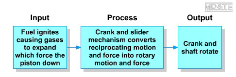
Mechanical systems have at least three elements: input, process and output.
- The input part of the system is any type of motion and force that drives the mechanical system. The input motion and force may be from any power source including human effort, energy from the wind, water, heat etc., from a chemical reaction or from an electrical, pneumatic or hydraulic device.
- The process part of the system is where mechanisms are used to convert the input motion and force into an output motion and force.
- The output is the change created in the input motion and force by the mechanism.
An image showing the Flash animation logo  is a
link to a Flash animation. is a
link to a Flash animation.
Flash animations are embedded into the pages of all my D&T Modules but there are pictorial links to the animations on this web site so that devices that cannot play Flash animations will at least show a jpeg screenshot of the animation.
If your PC or personal digital assistant (PDA) can play Flash animations you may click on an image showing the Flash animation logo  to view the animation in a new window. to view the animation in a new window.
(Your browser may require you to click "Allow Blocked Content" to view the animation). See info about viewing Flash animations. |
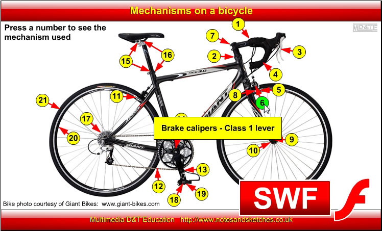
Example of mechanical system showing the INPUT, PROCESS and OUTPUT stages
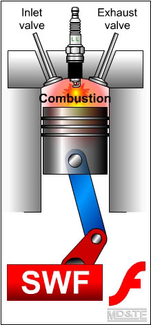
A simplified animated diagram of the crank and slider mechanism found in a single cylinder internal combustion engine is shown opposite.
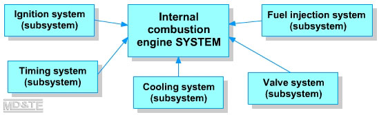
The system shown above is a small part of a larger and more complex system, e.g.
- In order for the fuel to ignite, an ignition system must be in place.
- The fuel must ignite at precisely the correct time so a timing system must also be in place.
- A measured amount of fuel must be injected into the combustion chamber at precisely the correct time so a fuel injection system must be place.
- Exhaust gases must be evacuated from the combustion chamber so a valve system must be in place.
An internal combustion engine is a system that gives a motor vehicle the power to move. The ignition system, the timing system, the fuel injection system and the valve system are subsystems of the internal combustion engine system.
Subsystems are systems that are part of a larger system. Mechanical systems usually comprise of a number of subsystems.
|
|
Click on the screenshot above to view the example mechanical system animation by Laszlo Lipot |
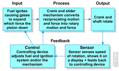
Feedback and control
The system described above consists of input, process and output elements that result in a crankshaft rotating. The system does not allow for control over the speed of rotation of the crankshaft. In order to control the speed of rotation, there must be a monitoring and control subsystem built into the system. This can be achieved by:
- using sensors to monitor the input part of the system and feeding the information to a controlling device that makes changes to the input
- using sensors to monitor the mechanisms in the process part of the system and feeding the information to a controlling device that makes changes to the input and/or the process part of the system
- using sensors to monitor the output part of the system and feeding the information to a controlling device that makes changes to the input and/or the process part of the system.
Examples of sensors used on a motor vehicle
Example 1
A sensor senses the speed of a vehicle and feeds information back to the driver through a speedometer. Feedback is through the speedometer. The driver has control of the vehicle and decides whether to increase, decrease or maintain current speed.
Example 2
A sensor senses the temperature of the internal combustion engine and displays the information on a meter (thermometer). The information is also fed to a controlling device. When the temperature reaches a predetermined point the controlling device switches on an electric fan that cools the engine. The fan continues cooling the engine until the engine temperature is back within normal working limits and is then switched off by the controlling device.
Example 3
An engine control unit (ECU) uses information from sensors together with settings programmed by the driver to control the fuel and ignition systems and so control the speed of the vehicle. Other uses of the control unit can be to:
- maintain a constant speed by the use of a cruise control
- maintain optimum revolutions of the crankshaft for any given driving condition
- control brake pressure to prevent the vehicle from skidding
- disengage vital systems in order to prevent theft of the vehicle.
Summary
Feedback and control of mechanical systems involves using
- sensors to monitor:
- the input
- the mechanisms in the process part of the system
- the output motion and force,
- feeding the information to:
- analogue or digital displays so that a human operator may act on the information; and/or
- controlling devices that act on the input and/or process parts of the system to achieve a desired output
|