Introduction
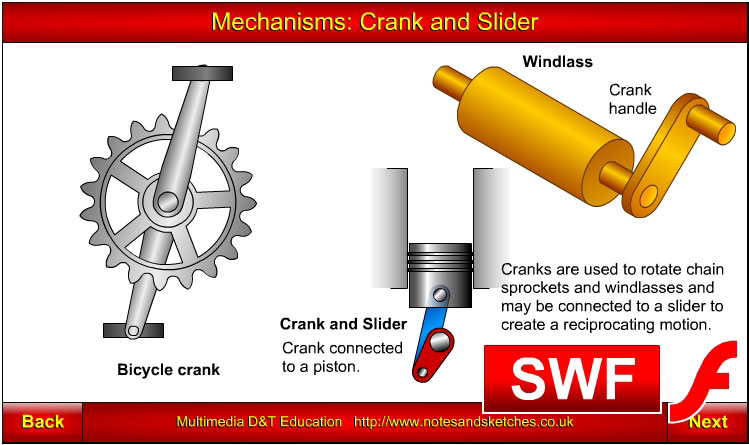
A crank and slider mechanism converts:
- rotary motion into reciprocating motion
- reciprocating motion into rotary motion.
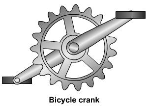
Crank
A crank is a lever that is attached to a shaft. It is used to apply torque to the shaft or conversely, when the shaft is rotating, torque is applied to the lever.
Two examples of cranks are illustrated above.
- Figure 1 shows a bicycle crank, that is part of a chain and sprocket mechanism on a bicycle. Force is applied to the pedals attached to the crank in order to apply torque to the centre shaft and sprocket attached to it.
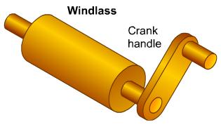
- Figure 2 shows a simple windlass used to haul rope that is usually would around a windlass. Modern versions of windlass mechanisms are used as yacht winches to haul the various ropes and steel cables (sheets and halyards) on yachts.
Both of the examples above illustrate force being applied to the crank handle/pedal in order to apply torque to a shaft.
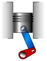
Slider
The most common type of slider used in crank and slider mechanisms is the piston used in internal combustion engines.
- Fuel is injected into a petrol engine cylinder.
- A spark causes the petrol to explode in the cylinder.
- The explosion forces the piston to move downward in the cylinder. A linkage called a connecting rod links the piston to the crank. The downward movement of the piston applies torque to the crank.
- As the crank rotates past the bottom of the stroke it begins to lift the piston to the top of the cylinder and push out the exhaust gases.
- A few degrees past the top of the stroke, the cycle is repeated, resulting in a continuous reciprocating motion of the piston and rotary motion of the crank / crankshaft.
|
|
|
In this example input linear motion and force from the piston is converted to rotary motion and force in the crankshaft. Kinetic energy of the rotating crankshaft lifts the piston back to the top of the cylinder resulting in a reciprocating motion of the piston.
Uses
An electric motor driven crank and slider mechanism with a reciprocating motion output can be used as:
- the basis of a testing device for:
- testing furniture drawer slides by repeatedly opening and closing drawers, tens of thousands of times
- testing door handles by repeatedly lowering and lifting the handle
- testing sash window slides by repeatedly lifting and lowering windows
- abrasion testing finishes on materials
- impact testing of products and materials where the effects of repeated impact or shaking will be measured
- abrasion testing fabrics by fixing an abrasive to a slider that reciprocates on the surface of the fabric
- the basis for tools that require a part such as a saw blade to move backward and forward repeatedly etc.
Summary
A crank and slider mechanism will convert a rotary motion and force into reciprocating motion and force.
A crank and slider mechanism will convert a reciprocating motion and force into rotary motion and force. |