GearsA gear is a toothed wheel that engages with:
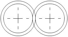
Gear wheels are called “spur gears” because the shape of gear wheels is similar to the shape of spurs used by some horse riders to help them control their horses. |
||||||
|
||||||
|
Preventing Gear Wheel Slippage on a Shaft
A gear wheel has a hole at the centre so that it may be fitted onto a shaft. To prevent the gear wheel from slipping on the shaft, a rectangular section steel bar called a "key" is placed into the slots called"keyways" in the gear wheel and shaft.
When the shaft is rotated, the key forces the gear to rotate with it. When the gear is rotated, the key forces the shaft to rotate with it.
The key prevents rotary slippage of the gear wheel on the shaft.
Using Gears
Gears provide a non-slip positive drive. They are excellent mechanisms for motion control.
Gears are used to:
- transmit motion and force from one shaft to another
- transmit motion and force from a gear wheel to a rack or from a rack to a gear wheel
- increase or reduce the rotary speed of the driven gear and shaft
- increase or reduce the torque of the driven gear and shaft
- increase or reduce the mechanical advantage (MA) of the driven gear and shaft.
Positive Drive
Meshed gears are interlocked so there cannot be slippage between the driver and driven gears. Gears have a positive drive because slippage is not possible.
A plain V-belt on a belt and pulley system can slip if it is not tight on the pulleys. A belt and pulley system does not have positive drive if it allows slippage. A toothed belt and pulley system provides a positive drive because it does not allow slippage.
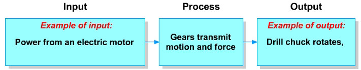
Using Gears to Transmit Motion and Force
Gears transmit motion and force from one shaft to another. Gears are used in mechanical systems to transmit motion and force from a power source to an output and in the process gears may give the mechanical system a mechanical advantage. The mechanical advantage may be:
- an increase or decrease in speed
- an increase or decrease in torque (rotary force).
Gear TrainTwo or more meshed gears are called a gear train. Gears in a gear train always have the same sized gear teeth, regardless of the diameter of the gear wheel or the number of teeth on it. Two adjacent meshed gears will always rotate in opposite directions. The gear that is fixed to an electric motor or other power device is called the driver gear and the other gear is called the driven gear. |
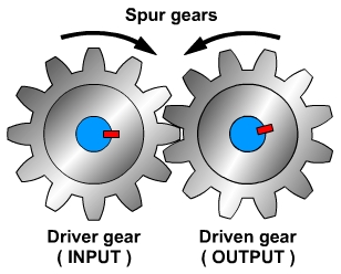 |
Input motion and force are applied to the driver gear. Output motion and force are transmitted through the driven gear.
A simple gear train has only one gear wheel on each gear shaft, a compound gear train has more than one gear on at least one gear shaft.
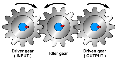
Idler Gear
An idler gear is a spur gear that is placed between the input gear and the output gear in a simple gear train.
The purpose of an idler gear is to:
- control the direction of rotation of the output gear
- span the gap between the input gear and the output gear when there is a gap between them.
Idler gears do not affect the velocity ratio of the driver and driven gears.
Gear Wheel and PinionWhen spur gears of different sizes are meshed, the larger gear wheel is called the wheel and the smaller one is called the pinion. In the example opposite, the wheel has 12 teeth and the pinion has 8 teeth. The pinion wheel will rotate one and a half revolutions for each revolution of the wheel. |
|
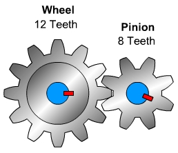 |
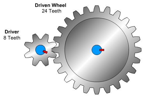
In the example below, the wheel has 24 teeth and the pinion has 8 teeth.
The pinion is the driver gear and the wheel is the driven gear. The pinion will rotate 3 times for each revolution of the wheel.
Velocity Ratio (VR)
As gears are used to transmit motion and force from one shaft to another, it is important to be able to calculate the velocity of the driven gear from the velocity of the driver gear.
When the velocity of the driver gear is known, the velocity of the driven gear may be calculated by using one of the two formulae below:
| 1. |
|
||
| 2. |
|
| Method 1. | Velocity ratio = |
distance moved by the effort (driver gear) |
In the diagram above, the driver gear has 8 teeth and the driven gear has 24 teeth. For 1 complete revolution of the driver the driven wheel moves 1/3 of a revolution, i.e. the driver revolves 3 times for every revolution of the driven gear.
Velocity ratio = |
distance moved by the effort (driver gear) = 1 |
= |
1 |
= |
3 |
The distance moved by the driver gear divided by the distance moved by the driven gear may be shown as a ratio, e.g.
velocity ration of |
3 |
|
| Method 2. | Velocity ratio = |
number of teeth on the driven gear |
For a simple gear train of two gears the velocity ration can be calculated by dividing the number of teeth on the driven gear by the number of teeth on the driver gear.
Velocity ratio = |
number of teeth on the driven gear |
= |
24 Teeth |
= |
3 |
= |
3:1 |
Gear Shaft Velocity
A key connects the drive shaft to the driver gear, so the drive shaft and driver gear rotate at the same velocity. A key connects the driven shaft to the driven gear, so the driven shaft and driven gear rotate at the same velocity.
If the gear with 8 teeth is fitted on the drive shaft and a gear with 24 teeth is fitted on the driven shaft, and the drive shaft rotates at a velocity of 600 revolutions per minute (RPM), what is the velocity of the driven shaft?
Velocity ratio = |
number of teeth on the driven gear |
= |
24 Teeth |
= |
3 |
= |
3:1 |
The driver shaft rotates at a velocity of 600 RPM, so:
distance moved by the effort (driver gear) |
= |
revolutions of driver shaft |
= |
600 |
Velocity ratio |
= |
3 |
= |
600 |
|
So, when the driver shaft has a velocity of 600 revolutions per minute (RPM), with a velocity ratio of 3:1, the driven gear will have a velocity of 200 RPM.
Mechanical Advantage
Mechanical advantage is the amount of force amplification achieved by using a tool, a mechanical device or mechanical system. Mechanical advantage of gears can be calculated using any of the formulae below:
1. |
|
||
2. |
|
||
3. |
|
||
4. |
|
Compound Gear Trains
Compound gear trains consist of two or more pairs of meshed gears, with the driven gear of one pair of gears being on the same shaft as the driver gear of the next pair of gears.
It can be seen in the illustration below that there is a driven gear and a driver gear on shaft B. As both gears are keyed onto shaft B, they must revolve at the same velocity.
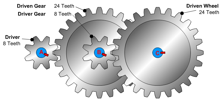
We have seen that a gear train with a driver gear that has 8 teeth and a driven gear that has 24 teeth, has a velocity ration is 3:1. If the driver gear has a velocity of 600 RPM, the driven gear on shaft B has a velocity of 200 RPM.
The second gear on shaft B also has a velocity of 200 RPM. The second gear on shaft B is the driver gear of the gear on shaft C. As the driven gear on shaft C has 24 teeth, the gear ration for the second pair of gears is also 3:1.
When the gear ratio is 3:1 and the velocity of the driver gear on shaft B is 200, the velocity of the driven gear on shaft C is 200 ÷ 3 = 66.66 RPM.
Therefore the ratio between the input and output is 9:1 (600 ÷ 66.66 recurring = 9).
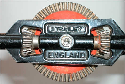
Bevel Gears
Bevel gears transmit motion and torque through an angle, often a right angle. The bevel gears on a Stanley hand drill are illustrated below.
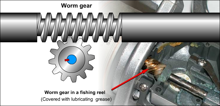
Worm Gears
Worm gears consist of a screw and a spur gear. The screw is meshed with the spur gear. As the screw revolves, it rotates the spur gear. The spur gear cannot turn the screw. The system only works by the screw turning the spur gear. The system is used in guitar string tensioning devices and tennis net cord tensioning devices, where the string is wrapped around the spur gear shaft.
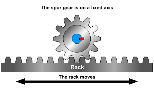
Rack and Pinion
A rack has teeth set in a straight line. When the pinion gear is rotated on a fixed axis the rack is forced to move.
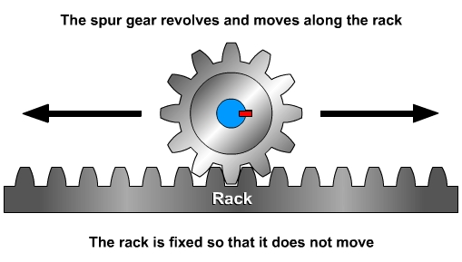
When the rack is fixed and the pinion is made to rotate, the pinion moves over the rack.
| Click here to view a PDF version of this resource. | 
|
 |