Introduction
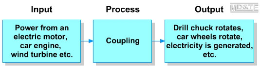
The output from power sources such as electric motors, car engines and wind generators is rotary motion of a drive shaft. The output rotary motion and force must be transmitted from the power source to a mechanism that will use the energy in some way. The usual ways of transmitting motion and force from the output drive shaft to a shaft in a mechanism is through:
- gears
- belt and pulleys
- chain and sprockets
- a crank
- couplings.
This section will explain how motion and force is transmitted from the output shaft of a power source through a coupling to other parts of a mechanism.
Couplings
Two or more shafts may be connected longitudinally in order to extend the overall length of the shaft and to transmit motion and force from one shaft to the other. The options for connecting shafts are:
- Shafts may be joined permanently or semi permanently.
- Shafts are joined permanently by welding or brazing.
- Shafts are joined semi permanently by using couplings.
Couplings connect two or more shafts longitudinally, i.e. one after the other and transmit motion and force from one shaft to another.
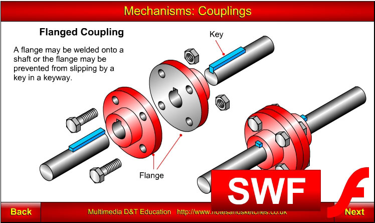
Flanged couplings
A flange is a disc attached to part of a shaft, usually the end. The flange may be fixed to the shaft permanently by welding or brazing, or it is prevented from rotating on the shaft by the use of a key fitted in a keyway. In addition to the key that prevents the flange from slipping on the shaft, the flange may also be clamped to it. |
|
|
Acknowledgements for coupling animation: http://en.wikipedia.org/wiki/File:Rotating_coupling.gif |
Two or more shafts with flanges fixed on the end can be bolted together. The bolts and the key take the shear forces exerted by the rotating shafts. The outer face of the flange must be perfectly at right angles to the shaft or it will create a misalignment when two shafts are bolted together.
Flexible couplings
Flexible couplings are used when two shafts are not perfectly aligned.
There are various types of flexible coupling, the simplest consists of a flexible rubber damper fitted between two flanges. Instead of bolting two flanges together, the flanges are bolted to the rubber damper. The flexible damper transmits motion and force from one flanged shaft to the other and is also able to absorb a small amount of vibration and shock.
Split coupling
A split coupling is a thick walled cylinder that has been split along its length and is fixed together using bolts.
The advantage of a split coupling is that it can be fitted to shafts that are difficult to move apart in order to fit a new flanged coupling.
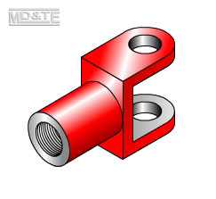
Clevis joint
A clevis joint may be fixed to a shaft permanently by welding or semi permanently by being screwed onto a shaft.
A clevis joint is fitted with a pin that allows a shaft to be moved in two directions, e.g. from side to side or up and down.
When two clevis joints are fitted together, a special joint called a universal joint is formed. |
|
|
Universal joint
The universal joint allows the greatest amount of misalignment between shafts and varying amounts of misalignment between shafts.
Acknowledgements for coupling animation: http://en.wikipedia.org/wiki/File:Universal_joint.gif |
|
|
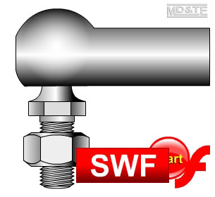
Ball and socket joint
Ball and socket joints are used as couplings.
Ball and socket joint consists of two main parts,
- a shaft with its end forged into a ball shape
- a shaft with a rounded hollow called a socket at its end.
The two parts fit together and are usually lightly held together with a clip.
The ball and socket coupling is used as part of a towing device fitted to cars and lorries, in motor vehicle steering mechanisms and other applications where there is a small amount of movement is required in the joint. |
|
| |
Click on the screenshot above to view the
"Ball and Socket" animation by Laszlo Lipot |
|
| |
|
| Click here to view a PDF version of this resource |

|
|
|