 |
|||
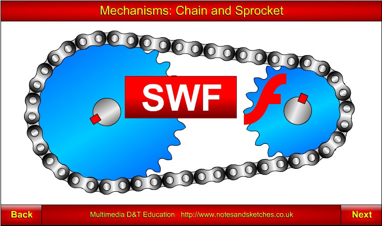
Click on the screenshot above to view the "Chain and Sprocket" animation by Laszlo Lipot |
|||
|
|||
IntroductionThe output from power sources such as electric motors, car engines and wind generators is rotary motion of a drive shaft. The output rotary motion and force must be transmitted from the power source to a mechanism that will use the energy in some way. The usual ways of transmitting motion and force from the output drive shaft to a shaft in a mechanism is through:
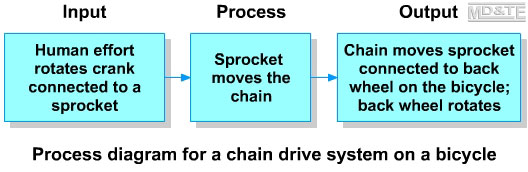
This section will explain how motion and force is transmitted from the output shaft of a power source through a chain and sprocket to other parts of a mechanism. Example: the chain and sprocket drive on a bicycle
Chain and SprocketA sprocket is a toothed wheel that fits onto a shaft. It is prevented from rotating on the shaft by a key that fits into keyways in the sprocket and shaft. A chain is used to connect two sprockets. One sprocket is the driver sprocket. The other sprocket is the driven sprocket. Motion and force can be transmitted via the chain from one sprocket to another, therefore from one shaft to another. Chains that are used to transmit motion and force from one sprocket to another are called power transmission chains. There are 6 major groups of power transmission chains:
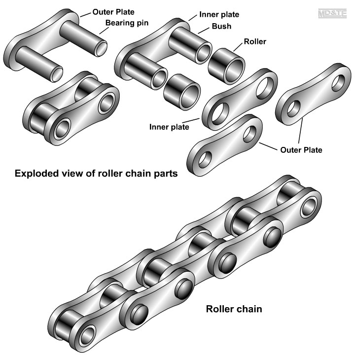
Most of these chains are the roller type, i.e. they are composed of link plates, pins that join the link plates and also rollers and bushes.
The size of the chain links must match precisely the size and spacing of the sprocket teeth. Advantage of chain drivesAn advantage of chain drives over most belt drives is that the chain cannot slip on the sprocket, so the chain and sprocket provides a positive, non-slip drive, i.e. the chain cannot slip on the sprocket because the sprocket teeth prevent the chain from slipping. Some belt and pulley drives also have teeth. These toothed belt and pulley drives are used in applications where it is important that the belt does not slide on the pulley, e.g. timing belts in internal combustion engines and the drive belts that replace the chain on some motorcycles. Disadvantage of chain drivesThe disadvantage of the chain and sprocket drive is that it can be noisy and more expensive than a belt and pulley drive system. Chain and sprocket drives are not used on some applications such as drilling machines and lathes precisely because the chain and sprocket drive does not allow slip. For safety reasons, belt and pulley drives are used on many machines so that in the event of something jamming in the machine, under great pressure, the belt can slip on the pulley rather than damaging the machine as would happen with a no-slip chain and sprocket drive. Chain and sprocket drives are used in applications where slipping should not occur, e.g.
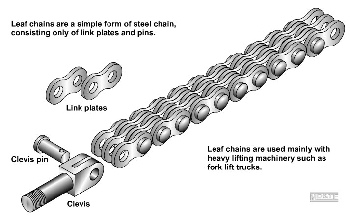
Leaf ChainsLeaf chains are a simple form of steel chain, consisting only of link plates and pins. Leaf chains are very strong, generally having greater tensile strength than roller chains. There are no rollers or bushes in leaf chains, simply links plates connected by pins. This means that leaf chains must be lubricated regularly and must only be used for low speed applications such as raising and lowering the forks of a fork lift truck.
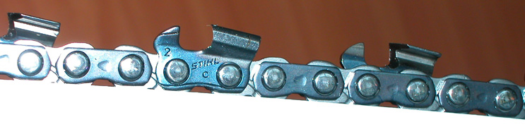
Leaf chains run over sheaves, (which are similar to pulleys) rather than over sprockets. The chain is fitted with a clevis at each end held in place by a clevis pin. The clevis is used to fix the chain to other parts of machinery, often hauling and lifting systems. Special ChainsThere are variations of the basic link and pin system of chains, with the modifications making the chain suitable for applications such as escalators, conveyors and chain saws (see photo below). Every second link in a chain saw chain has a specially shaped link that cuts timber.
|
|||
| Click here to view the PDF version of this resource. | 
|
 |
|